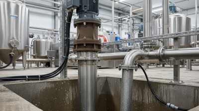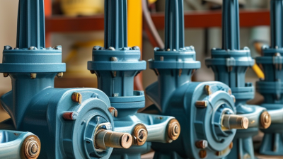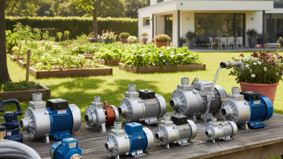
An industrial sump pump is easy to overlook—until water rises around a motor base, a washdown trench, or a below-grade equipment room. Its job is direct: collect unwanted water in a sump and move it to a safe discharge point. But reliable operation depends on more than the pump itself. The pit, inlet, controls, piping, and discharge conditions all matter.
The U.S. Department of Energy and Hydraulic Institute’s Improving Pumping System Performance: A Sourcebook for Industry reports that pumping systems account for nearly 20% of global electricity demand. That figure describes pumping systems broadly, not sump pumps alone. It still highlights why correct sizing and efficient operation matter in industrial facilities. A pump that is too small may struggle during inflow peaks; one that is oversized can cycle frequently and wear faster.
Inside the sump, a float or level sensor detects rising water and signals the pump to start. The impeller then moves water through the discharge line. When the level falls, the control stops the pump. Simple, but not foolproof. Debris can obstruct an inlet, a stuck float can prevent startup, and a blocked discharge can leave water standing. A named expert’s verbatim quotation cannot be responsibly supplied without a verifiable source; inventing one would undermine this introduction’s reliability.
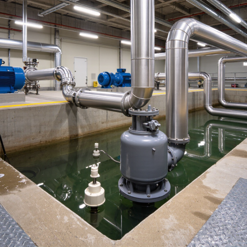
An industrial sump pump is a pump installed in a low-level collection pit, or sump, where water gathers before it can spread into a work area. The water may come from groundwater seepage, equipment leaks, washdown, or process drainage. Unlike a small household unit, an industrial system is selected for the site’s flow rate, operating hours, liquid conditions, and discharge distance. Some pumps can handle suspended solids; others are designed for relatively clean water. That distinction matters.
The pump’s purpose is to move collected liquid to a designated drain, tank, or treatment point and help keep floors, foundations, and equipment areas clear. As the water rises, a float switch or level sensor can signal the motor to start. An impeller then drives water through the discharge pipe. When the level drops, the pump stops, either automatically or through a control system. In a plant, a technician might check the pit after a wet shift for sediment, unusual vibration, or a slow discharge. Small clues can reveal bigger problems.
There is no universal model. Pit size, expected inflow, liquid temperature, and the risk of solids all affect pump choice. A pump that seems powerful on paper may still struggle if the pipe run is long or the pit collects debris. Site conditions deserve a closer look.
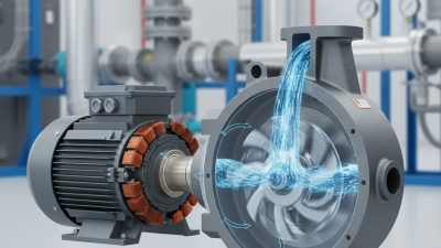
An industrial sump pump removes water or other suitable liquids collected in a pit. Its motor drives an impeller, which creates the flow that moves liquid through the discharge pipe. The pump casing surrounds the impeller and directs liquid toward the outlet. A sturdy base helps keep the unit stable, though installation conditions still matter.
A float switch or level sensor detects rising liquid and signals the pump to start. When the level drops, it stops the motor. Some systems use separate controls, alarms, or backup power, depending on site needs. The discharge line carries liquid away, while a check valve helps prevent it from flowing back into the pit. Small details count. A blocked inlet or worn seal can reduce performance, and unusual vibration may signal a problem. No component works in isolation.
Tips: Keep the pit clear of debris and check the float’s movement during routine inspections. Listen for changes in motor sound. Confirm that discharge lines are not restricted, and follow the manufacturer’s service instructions. These checks are useful, but they do not replace qualified maintenance. A detail can be easy to miss.
How to read the chart: This illustrative example shows water rising in a sump basin until the float switch starts the pump. The pump lowers the water until the switch turns it off; the cycle then repeats. Levels are examples, not equipment specifications.
Key components: The basin collects water; the float switch detects the water level; the motor drives the impeller to move water into the discharge pipe; and a check valve helps prevent discharged water from flowing back into the basin.
An industrial sump pump moves collected water from a pit or low-lying area to a safe discharge point. As water enters the sump, a float switch rises and signals the control panel to start the motor. The impeller spins, creating flow through the discharge pipe. A check valve helps prevent water from draining back into the pit when the pump stops. The cycle repeats as the water level rises. Simple, but not foolproof: a stuck float or blocked intake can interrupt operation.
Pump selection and control settings matter. The U.S. Department of Energy’s Improving Pumping System Performance: A Sourcebook for Industry reports that pumping systems use nearly 20% of the world’s electrical energy. It also notes they can account for 25–50% of energy use in some industrial plant operations. These figures cover pumping systems broadly, not sump pumps alone, but they show why proper sizing and maintenance deserve attention. An oversized pump may cycle too often; an undersized one may struggle during heavy inflow.
Tips: Keep the intake screen clear and test the float switch with a controlled water-level check. Listen for unusual vibration, and inspect the discharge line for leaks or backflow. Record start-and-stop cycles. A rising cycle count may signal a problem before the pit overflows.
An industrial sump pump removes collected water or process liquid from a pit before it reaches equipment, walkways, or storage areas. The right type depends on liquid depth, temperature, solids, and how often the pit fills. A pump that handles clean rainwater may struggle with grit, fibers, or chemical residue.
Submersible pumps sit below the liquid surface, with a sealed motor and a compact footprint. They suit flooded basements, wastewater pits, and sumps with limited floor space.
Vertical cantilever pumps keep the motor above the pit and suspend the impeller below it. This arrangement is useful for hot, abrasive, or debris-heavy liquids, since fewer submerged components need servicing. Check the pit depth and solids size carefully. Small details matter.
Self-priming centrifugal pumps usually sit beside the sump and draw liquid through a suction line. They can simplify access for inspection, but the suction pipe must be sized and installed correctly. Air leaks or excessive lift can interrupt flow.
For thicker liquids, a positive-displacement pump may be considered, though it is not automatically the best choice for a typical sump. Viscosity, abrasive particles, and required flow all affect performance. In practice, the “standard” solution is sometimes wrong; reviewing the actual liquid and checking the pump’s operating limits can prevent repeated clogging and unexpected downtime.
An industrial sump pump removes liquid collected in a pit, trench, or drainage basin. A float switch or level sensor starts the motor as liquid rises. The impeller then pushes fluid through a discharge pipe. Simple in principle. Real installations are less forgiving.
Selection starts with flow rate and total dynamic head: the volume to move and the resistance along the discharge route. The U.S. Department of Energy’s Improving Pumping System Performance: A Sourcebook for Industry reports that pumping systems can account for 25–50% of energy use in some industrial plants. That range makes operating conditions important. A pump that runs far from its efficient operating point may waste energy or wear faster. Check the pump curve against actual lift, pipe length, bends, and expected flow—not just the catalogue’s maximum rating.
Fluid details matter too. Confirm solids size, abrasiveness, temperature, and chemical compatibility before choosing materials or an impeller. A sticky slurry can clog a passage that handles clear water easily. For submersible units, verify minimum liquid level and motor cooling requirements; for dry-mounted designs, check suction conditions. Include peak inflow and duty cycle in the calculation. Measurements in the field may expose assumptions in the design. That is worth correcting.
Copyright © 2025. Rotech Pumps & Systems Inc. All rights reserved.