Choosing among the types of pumps is not a catalog exercise. It is an engineering decision with real effects on energy use, reliability, and maintenance. The U.S. Department of Energy’s Improving Pumping System Performance sourcebook reports that pumping systems can account for 25–50% of energy use in some industrial facilities. That range depends on the plant, but it shows why pump selection deserves careful attention. A pump that looks suitable on paper may waste energy if it operates far from its best-efficiency point. Small mismatch. Big cost.
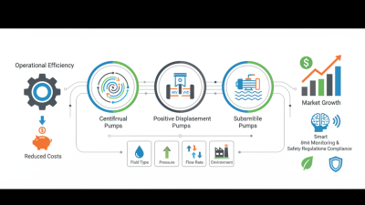
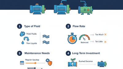
The right choice starts with the duty: required flow rate, total head, operating hours, and fluid properties. Centrifugal pumps often suit steady flows of low-viscosity liquids. Positive-displacement designs can be better for viscous fluids or precise dosing. Submersible pumps handle applications where the pump must operate underwater, while diaphragm pumps can serve demanding transfer tasks. These are starting points, not fixed rules. Temperature, solids, corrosion, suction conditions, and maintenance access can change the answer.
This guide explains how to compare pump types against actual operating requirements. It also highlights details buyers sometimes overlook, such as variable demand, seal compatibility, and lifecycle cost. A pump should be sized for the system, not just its nameplate flow. Real installations are rarely perfect. Confirming assumptions with operating data and a qualified pump specialist can prevent an expensive mismatch.
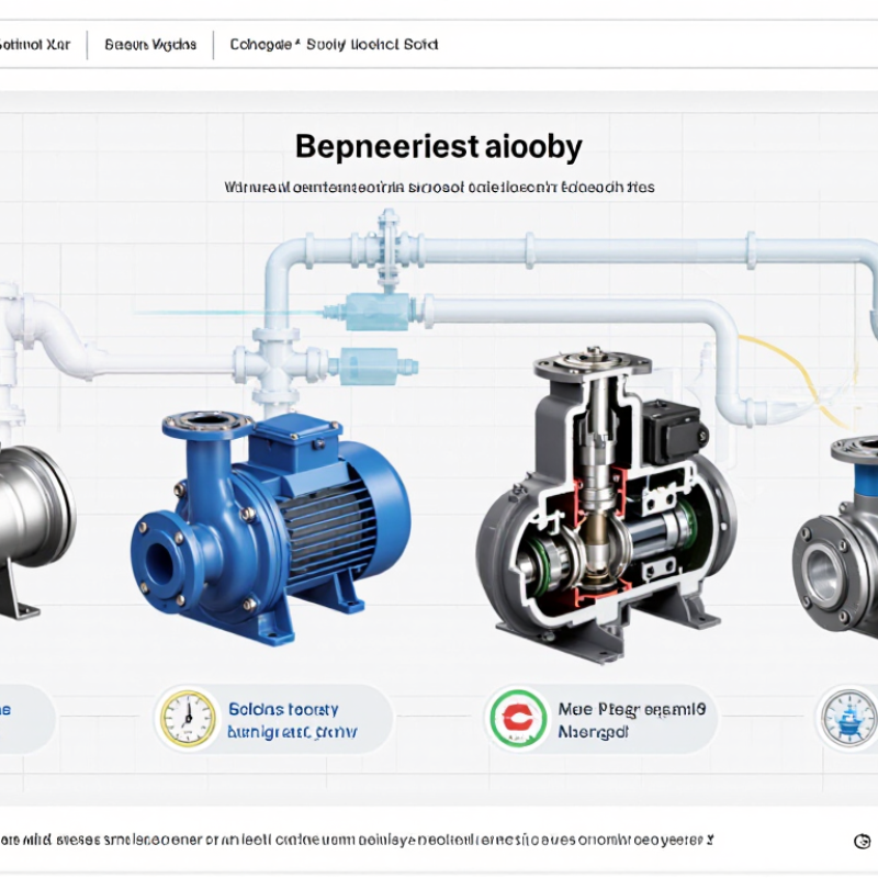
A pump should be selected around its duty point, not just its pipe size or motor rating. The duty point combines the required flow rate with the total dynamic head (TDH). Flow describes how much liquid must move over a set time, such as 40 gallons per minute. TDH is the energy the pump must add to move that liquid through the system. Start with the actual operating need. A guess can lead to poor performance.
To estimate TDH, include the vertical lift from the liquid source to the discharge point, plus friction losses in pipes, elbows, valves, and filters. A long, narrow pipe may need more head than a short, wide one. Add the pressure required at the outlet, too. Pressure and head are related, but they are not interchangeable without accounting for the liquid’s density. Small errors grow. Check the figures against real pipe routes and equipment data where possible.
Then compare the duty point with the pump’s performance curve. The chosen pump should deliver the required flow at the calculated head, preferably near its efficient operating range. Conditions matter: liquid temperature, viscosity, solids, and changes in demand can shift performance. I have seen designs rely on a single ideal flow figure, only to find that a partly closed valve changes the result. Recheck assumptions. A modest allowance for uncertainty may help, but excessive oversizing can waste energy and create control problems.
Pump selection starts with the liquid, not the catalog. Measure viscosity at the actual operating temperature, and note whether it changes during the process. The U.S. Department of Energy’s 2006 Improving Pumping System Performance sourcebook estimates that pumping systems use nearly 20% of global electricity, and 25–50% of energy in some industrial plants. Those figures make accurate duty data more than paperwork.
Thick syrup or oil can reduce a centrifugal pump’s flow and efficiency; a positive-displacement design may suit it better. Check the Hydraulic Institute’s guidance on viscosity effects before final sizing. For solids, record particle size, concentration, and whether particles are abrasive or stringy. A few hard grains can wear tight clearances quickly. A neat chart cannot replace a sample.
Temperature changes viscosity, vapor pressure, and seal limits. Hot liquids may increase cavitation risk, so verify available NPSH against the pump’s requirement. Corrosiveness also depends on concentration and temperature, not pH alone. Match wetted materials to the full chemical mixture, including cleaning fluids. I would confirm uncertain details with a trial. That step is easy to overlook. Keep test results, operating temperature, and fluid composition with the pump specification; otherwise, a technically sound selection may still fail in service.
| Fluid Example | Typical Viscosity | Solids | Typical Temperature | Corrosiveness | Pump Type to Consider | Selection Notes |
|---|---|---|---|---|---|---|
| Clean water | Low; close to 1 mPa·s at room temperature | None or negligible | Ambient | Low for compatible materials | Centrifugal pump | A common choice for steady, high-flow transfer. Confirm the required flow, head, and water chemistry. |
| Light hydrocarbon solvent | Low | None | Ambient to moderately warm | Depends on solvent and wetted materials | Centrifugal pump or magnetic-drive centrifugal pump | Check seal compatibility, vapor pressure, flammability requirements, and the pump’s operating conditions. |
| Lubricating oil | Low to moderate; varies significantly with grade and temperature | Usually none; may contain fine contaminants | Ambient to warm | Usually low for compatible materials | Gear pump or other rotary positive-displacement pump | Positive-displacement designs can suit metered or steady oil transfer. Use appropriate filtration and viscosity limits. |
| Molasses or concentrated syrup | High; strongly affected by temperature | May contain small particles | Often warmed to improve flow | Usually low, but cleaning requirements matter | Lobe pump or progressive cavity pump | Use a pump designed for viscous, shear-sensitive product. Verify startup torque, suction conditions, and cleanability. |
| Wastewater with soft solids | Low to moderate | Fibers and suspended solids | Typically ambient | May be mildly corrosive | Solids-handling centrifugal pump | Check the required solids passage, risk of clogging, and abrasion from grit. A screening step may be needed. |
| Sand-laden slurry | Higher than water; varies with solids concentration | High, abrasive solids | Typically ambient | Often abrasive rather than chemically corrosive | Slurry centrifugal pump | Select wear-resistant wetted parts and allow for reduced component life. Account for slurry density and settling. |
| Food-grade cream or soft product | Moderate to high | None or soft particulates | Chilled to warm, depending on process | Usually low; cleaning chemicals may be aggressive | Sanitary lobe pump | Consider gentle handling, hygienic design, clean-in-place requirements, and the temperature of cleaning cycles. |
| Hot condensate or hot water | Low | Usually none | Elevated; may be near boiling at operating pressure | Usually low, depending on water chemistry | High-temperature centrifugal pump | Check pressure, vapor formation, seal and material temperature ratings, and available suction pressure. |
| Acid or caustic process solution | Usually low to moderate | Usually none | Ambient to elevated | High; depends on chemical concentration and temperature | Diaphragm pump or compatible centrifugal pump | Confirm chemical compatibility for every wetted component, including seals, valves, and elastomers; do not select by fluid name alone. |
| Viscous, abrasive sludge | Moderate to high; may be non-Newtonian | High; solids may be fibrous or abrasive | Ambient to warm | Variable | Progressive cavity pump or other solids-capable positive-displacement pump | Evaluate solids size, concentration, shear sensitivity, and dry-running risk. Provide suitable wear protection and operating controls. |
Selection note: Viscosity and temperature values are indicative, not pump limits. Final selection should use the actual fluid composition, flow rate, pressure, suction conditions, solids size and concentration, and material-compatibility data.
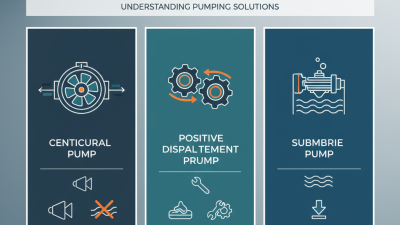
Choosing a pump family begins with the fluid and the job, not the catalog label. Centrifugal pumps suit many steady transfers of low-viscosity liquids. Their rotating impeller adds velocity, while the piping system affects the flow delivered. They can be a practical choice for water or similar fluids, but solids, gas, and changing viscosity may complicate performance. Check the pump curve against the actual operating point.
Positive-displacement pumps move a defined volume with each cycle or rotation. They often work well with viscous fluids, controlled dosing, or applications needing steady flow across changing pressure. However, a blocked discharge can create dangerous pressure, so suitable pressure protection matters. Real systems are rarely tidy. A datasheet may not reflect cold starts, trapped air, or a line that slowly clogs.
Specialty pumps address conditions that standard designs handle poorly, such as abrasive slurries, delicate shear-sensitive fluids, or precise small-volume transfer. The right mechanism depends on the details: particle size, temperature, cleaning routine, and allowable pulsation. Ask operators what they actually see at startup and during shutdown. That conversation can expose a mismatch before a pump is installed. A small trial with the real fluid may also reveal wear or flow behavior that calculations miss.
2026 How to Choose the Right Type of Pump?
Compare Efficiency at the Best Efficiency Point (BEP)
A pump’s BEP is the flow and head where it runs most efficiently. Compare candidate pumps using their published efficiency curves, not just motor ratings. The U.S. Department of Energy’s Improving Pumping System Performance sourcebook reports that pumping systems use nearly 20% of global electrical energy. Small differences matter. A pump operating far from its BEP can waste energy and experience greater vibration, noise, and wear. Check the expected operating range against the curve, including low-demand periods when a system may run at reduced flow.
For a practical comparison, match each pump’s BEP to the system’s usual duty point, then assess efficiency across normal variations in flow. Hydraulic Institute guidance emphasizes evaluating the pump’s operating region, since acceptable limits vary by design. Ask suppliers for test data at relevant speeds and impeller sizes; compare total input power, not efficiency in isolation. Also account for fluid temperature and viscosity, which can shift performance. A tidy curve is useful, but real installations are messier. Recheck assumptions against measured pressure and flow after commissioning.
Compare indicative efficiency ranges at the Best Efficiency Point (BEP) for common centrifugal pump types.
These broad, illustrative ranges are not guaranteed performance figures. Actual efficiency depends on pump size, operating conditions, and hydraulic design. Compare verified performance curves at your required flow and head, and select a pump that operates close to its BEP.
At a fixed impeller diameter, pump affinity laws estimate how performance changes with rotational speed. Double the speed, and theoretical flow roughly doubles, head rises about fourfold, and shaft power demand approaches eightfold. That is a steep trade-off. These estimates assume comparable operating conditions and fluid properties. They do not guarantee twice the delivered flow. Pipe friction, valves, elevation, and the system curve all affect the actual operating point. On paper, the ratios look clean. Real pipework is less tidy.
For example, a pump delivering 10 cubic metres per hour at 10 metres of head might be estimated to deliver 20 cubic metres per hour at 40 metres after a speed doubling. Its power demand could approach eight times the original level. That example is not a speed-change instruction. Check the pump curve, motor capacity, pressure limits, vibration, and available suction head before adjusting speed. A variable-speed drive can help with controlled changes, but it cannot remove equipment limits. I would verify the readings under real operating conditions; calculations alone can miss a troublesome detail.
Copyright © 2025. Rotech Pumps & Systems Inc. All rights reserved.